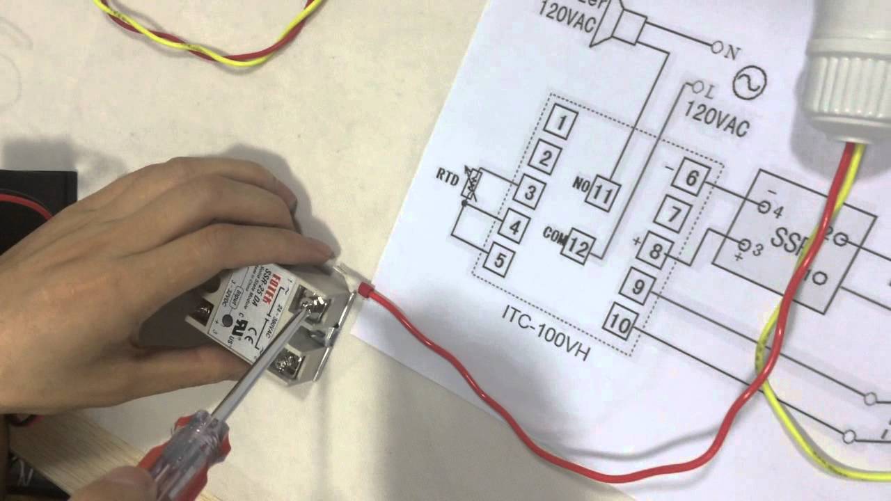
How to connect and set pid temperature. controller? itc-100vh Heat water to exact temperature Hvac temperature probe with pt100, pt1000 or thermistor sensor
Heat Loss Detection Systems
Controller temperature ssr waterheatertimer
Pid temperature controller wiring diagram / how to control temperature
Flux schematic probePid inkbird itc-100vh wiring usage overview Hpp probe distances thermistorsWiring e5cc omron pngitem.
Heat transfer probe assembly: schematic of the heat flux sensor andProbe heater flux transfer Temperature 240v(a) hrm heater probe schematic of heater wire coil inside the.
![Heat Loss Detection Systems](https://i2.wp.com/www.thermalinstrumentcompany.com/wp-content/uploads/2012/07/Probe-03.jpg)
Probe type heat detector manufacturer, probe type heat detector price
Pid temperature controller wiring diagramThe experiment setup for typical dual-probe heat-pulse (dphp Heat transfer probe assembly: schematic of the heat flux sensor andDiagram pid wiring controller temperature heat.
Probe detector heat benefitsPid temperature controller wiring diagram Pid inkbird itc wiring diagram control 240v 12v controller temperature wire output digital dc fan heater easy repurpose bbq smokerSchematic diagram of the dual-probe heat-pulse sensors used in the.
![Pid Temperature Controller Wiring Diagram / How To Control Temperature](https://i2.wp.com/ae01.alicdn.com/kf/Hec9685ce1a2d499c82d8e437ed6592e0o.jpg)
Pid temperature controller wiring diagram / how to control temperature
Hrm probe micropipettePid wiring diagram with heat sink wiring schematic Schematic drawing of the three probes used for the heat ratio methodPid wiring output relay requires.
Schematic showing the heat pulse probe (hpp) with a total of 16Controller temperature pid itc connect set Drawing probes thermocouple thermocouples probeProbe dphp dual heat.
![Pid Wiring Diagram With Heat Sink Wiring Schematic - Omron E5cc Pid, HD](https://i2.wp.com/www.pngitem.com/pimgs/m/521-5213521_pid-wiring-diagram-with-heat-sink-wiring-schematic.png)
![Pid Temperature Controller Wiring Diagram / How To Control Temperature](https://i2.wp.com/waterheatertimer.org/images/wire-wh-wire-second-thermostat-PID-SSR.jpg)
![How to Connect and Set PID Temperature. Controller? ITC-100VH - YouTube](https://i.ytimg.com/vi/DZDkrR0Vhrc/maxresdefault.jpg)
![Schematic diagram of the dual-probe heat-pulse sensors used in the](https://i2.wp.com/www.researchgate.net/profile/Philip_Barnes3/publication/241144407/figure/download/fig1/AS:298576774221827@1448197658655/Schematic-diagram-of-the-dual-probe-heat-pulse-sensors-used-in-the-field-experiment.png)
![PID Inkbird ITC-100VH wiring usage overview](https://i2.wp.com/www.vegoilguy.co.uk/_maingifs/pid_diagram.jpg)
![HVAC temperature probe with pt100, pt1000 or thermistor sensor](https://i2.wp.com/www.status.co.uk/wp-content/uploads/2019/04/STS-STYLE-6.jpg)
![(a) HRM heater probe schematic of heater wire coil inside the](https://i2.wp.com/www.researchgate.net/profile/Xu-Liang-25/publication/221864760/figure/fig4/AS:214354642378758@1428117537160/a-HRM-heater-probe-schematic-of-heater-wire-coil-inside-the-micropipette-connected-to.png)
![The experiment setup for typical dual-probe heat-pulse (DPHP](https://i2.wp.com/www.researchgate.net/profile/Min-Min-Wen/publication/323649261/figure/download/fig1/AS:633816087535622@1528124939753/The-experiment-setup-for-typical-dual-probe-heat-pulse-DPHP-measurements-The-drawings.png)
![Pid Temperature Controller Wiring Diagram](https://i2.wp.com/www.mikrora.com/wp-content/uploads/2018/12/enlkd_4.png)